If you’ve ever held a lightweight, rigid component for a drone, medical device, or semiconductor assembly, you know how game-changing thin-walled parts are. But anyone who’s tried to machine these parts knows the flip side: one wrong cut, and you’re left with a warped, unusable hunk of metal that’s wasted time, material, and money. As a supplier of precision machined components—what you might know as a “by machining” partner, we’ve spent the last 12 years troubleshooting thin-wall challenges for industries that can’t afford to compromise on accuracy. Today, I’m pulling back the curtain on what actually works for thin-wall machining, not just the generic tips you’ll find in a factory manual. By Machining
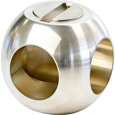
First, let’s define what a “thin wall” actually means here. We’re not talking about a flimsy soda can; we’re talking about walls 0.5mm thick or less, often in parts that are 100mm or more in diameter or length, with tight tolerances (think ±0.02mm) that can’t shift even a hair. The biggest enemy here is chatter and deflection—when the thin part vibrates or flexes mid-cut, leaving uneven walls, surface scratches, or dimensional errors. I once had a client in the aerospace sector send us a set of titanium fuel line housings for testing. Their previous shop had machined half the batch with walls 0.8mm thick, but 60% of them warped so bad they couldn’t fit the assembly. That’s the kind of problem that makes thin-wall machining feel like guessing, but it’s not—it’s about controlling every variable in the process.
Let’s start with stock selection and setup, because you can’t fix a bad foundation mid-machine. A lot of shops grab a raw billet and start cutting, but that’s a recipe for thin-wall failure. For parts where we’re machining walls down to 0.3mm, we always use solid billet stock rather than hollow tubing, even if the final part is a tube. Why? Tubing has inherent inconsistencies—thicker spots along its length, micro-defects from the extrusion process—that force the tool to adjust unexpectedly mid-cut, triggering deflection. Solid billet gives us a uniform starting point, which we can pre-condition to reduce internal stress. That’s a big one: when you machine a part, you’re releasing the internal stresses that were locked in during forging, rolling, or heat treating. For aerospace-grade aluminum or titanium, we always perform a stress relief anneal on the billet before machining, then leave a 0.2mm “guard band” on all surfaces until the final pass. That guard band absorbs stress release without letting a small shift ruin the part.
Setup is equally critical. Too many people clamp thin parts at the ends with standard vises, which creates pressure points that bow the center of the wall like a banana. Our go-to for thin-walled cylindrical parts is a custom-machined collet or a vacuum chuck. Wait—vacuum chucks? Yes, but not for every material. For aluminum and soft steel, a vacuum chuck distributes clamping force evenly across the entire back face of the part, so there’s no localized pressure causing warping. For harder materials like Inconel or stainless steel, we use a segmented collet that clamps in small, even sections along the outer diameter, not just the top and bottom. We also never use more clamping force than needed; if you can feel the part shifting slightly when you touch it with a non-marring tool, you’re clamping too hard. I learned that lesson early on: in 2017, we had a medical device client with a thin-walled titanium implant part that we clamped with 1500N of force, only to find it was bowed 0.1mm after machining. That error cost us 12 parts and a client’s trust—so now we calibrate clamping force for every thin-wall job, usually setting it to just enough to hold the part during tool changes, not full machining passes.
Next up: tooling and cutting parameters, where small adjustments make huge differences. For thin walls, you want a tool that’s rigid but has sharp edges—dull tools cause friction, which generates heat and makes the part flex. We almost always use solid carbide end mills with a high helix angle (40° to 45°) and a small number of flutes (2 or 3) rather than the 4 or 6 flutes you’d use for a thick part. Why? Fewer flutes mean more space for chip evacuation, so the tool doesn’t get clogged with tiny, thin chips that can scratch the wall or apply uneven force. For example, when machining a 0.3mm wall in 6061 aluminum, a 2-flute, 10mm diameter end mill works far better than a 4-flute one because the chips are small and can escape without packing between the flutes.
Cutting speed and feed rates are non-negotiable here, too. Too fast, and the tool will chatter against the thin wall; too slow, and the friction will overheat the material, softening it and causing deformation. We use a formula based on material hardness and wall thickness: for walls under 0.5mm, we run cutting speeds at 70-80% of the recommended maximum for the material, and feed rates at 50-60% of standard. For titanium thin walls, that’s a bit trickier—we’ve found that running at 65 m/min instead of the standard 90 m/min reduces tool deflection by 30% while keeping surface finish smooth. We also use climb milling exclusively for thin walls. Conventional milling pulls the tool against the wall, which can pull material away or cause chatter; climb milling pushes the tool into the cut, directing force away from the thin wall and toward the solid part of the stock, where it can’t do damage.
The final step in the process is the most important for avoiding post-machining distortion: the finishing pass. This is where that guard band I mentioned earlier comes in. After roughing out the part, leaving that 0.2mm layer, we do a series of semi-finishing passes to get within 0.05mm of the final wall thickness, then wait 12 to 24 hours before doing the final pass. Why wait? Because the machining process introduces residual stress, which takes time to stabilize. If you do the final pass right after semi-finishing, even a tiny shift in stress will throw your wall thickness off by more than tolerance. We also use a “shallow cut” final pass: instead of cutting 0.1mm deep, we cut 0.03mm, so the tool is removing minimal material, not applying enough force to flex the wall. On our aerospace parts, this has cut post-machining warpage by 90% compared to our old process.
But here’s the thing: no two thin-wall parts are the same. A 0.3mm wall in aluminum is way different from a 0.3mm wall in Inconel, and a cylindrical thin housing is way different from a flat, thin-walled bracket. That’s why, as a by machining partner, we never apply a one-size-fits-all process. Last year, we got a job for a semi-conductor client that needed thin-walled ceramic carriers—ceramic is even trickier than metal, because it’s brittle and can crack if too much force is applied. We tested three different tool geometries, two different clamping methods, and five sets of cutting parameters before landing on a process that worked for their specific carrier design. The client had been quoted a 40% scrap rate by another shop; we delivered the first batch with a 2% scrap rate.
I know a lot of machinists will read this and say, “I already do all that.” But I’d bet if you ask them, they’ve still thrown away a thin-wall part because of a last-minute vibration or a hidden stress in the stock. The secret to successful thin-wall machining isn’t just following the rules—it’s testing every variable for your specific part, and treating the process like a partnership between you, the machine, and the material. When we work with a new client on a thin-wall job, we always do a pilot run with 5-10 parts first, not full production, to work out any kinks before investing in a full batch. That’s how we avoid wasting money on bad parts, and how our clients get parts that meet their exact specifications, no compromise.
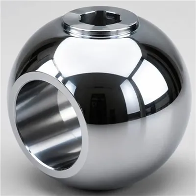
At the end of the day, thin-walled parts are what make modern technology light, efficient, and effective—whether it’s a drone that flies farther, a medical implant that fits better, or a semiconductor that processes data faster. Machining them well isn’t just a skill; it’s a responsibility. If you’re working on a project that needs precision thin-walled components and you’re tired of dealing with scrap parts, inconsistent quality, or long lead times, we’re here to help. Reach out to talk through your project, share your specs, and see how we can deliver parts that meet your exact needs without the headaches.
Valve Balls References:
- Kalpakjian, S., & Schmid, S. R. (2020). Manufacturing Processes for Engineering Materials. Pearson Education.
- DeVries, W. R. (2018). Analysis of Material Removal Processes. Springer.
- ASM International. (2019). Machining of Thin-Walled Components. ASM Handbook, Volume 16: Machining.
Zhejiang Jigong Valve Co., Ltd.
Address: Dongou Industrial Park, Oubei Subdistrict, Yongjia County, Wenzhou City, Zhejiang Province (within Zhejiang Yinhe Machinery Manufacturing Co., Ltd.)
E-mail: Sales@cnzjsk.com.cn
WebSite: https://www.ball-china.com/
